Electrical resistivity instrumentation.
These links will take you to information about the following instruments (includes picture, description, specifications, sample packing lists, weights & dimensions, rental rates, and user manuals):
AGI SuperSting R8
AGI Ministing or Sting R1
Geometrics OhmMapper
Home Page
Warning: the instrument specifications below are provided as a courtesy. Actual values may vary and need to be confirmed via the manufacturer.
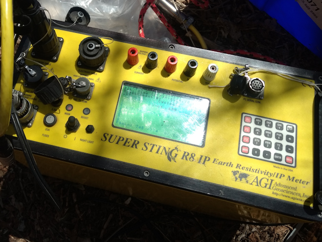
AGI SuperSting R8 Electrical Resistivity System
Description:
The SuperSting R8 is a multichannel soil electrical resistivity meter. Though known for its electrical resistivity imaging or tomography capabilities, it works well for demanding four pin or four electrode resistivity soundings. In the simplest terms during a simple sounding, the electrical resistivity meter injects current into the ground and measures the electrical resistance between two points with metal electrodes, usually made of stainless steel. Since different soil conditions and rock types have different electrical resistances, the subsurface can be characterized by measurements of apparent resistance. The system responds to various depths by changing the distance between electrodes.
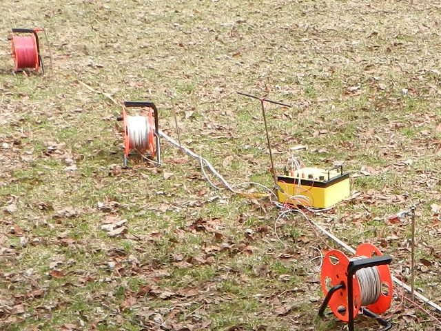
The SuperSting R8 electrical resistivity system possesses eight receiver channels. This means that for each current injection the meter simultaneously measures the electrical potential or voltage between eight pairs of electrodes, thus speeding up the measurement process. Furthermore, this electrical resistivity system has cable sets of 28, 42, 56, 60, or 84 takeouts (others configurations available upon request) with a switch box. This setup allows a myriad of permutations for quick and accurate measurements from a variety of depths and locations to produce high quality 2-D or 3-D electrical resistivity images.
The SuperSting R8 electrical resistivity system is good for mineral exploration, geotechnical and civil engineering investigations, groundwater exploration, bedrock and landfill mapping, and other environmental and monitoring investigations.
The SuperSting R8 electrical resistivity system is a good choice for 4 pin electrical resistivity surveys that require a powerful meter to reach greater depths using large electrode spacings (e.g. Wenner A-spacings).
Special Considerations:
Do not operate the SuperSting R8 during a thunderstorm!
About 240,000 people are injured by lightning strikes each year. One estimate is that the annual global death toll is 6,000 (Wikipedia). Consequently, one should take extreme care if there is lightning. Furthermore, thunder indicates the presence of lightning. If a thunderstorm should come up while out in the field with this electrical resistivity instrument, then remember to first stop ongoing measurements and then disconnect the cables from the terminals without touching any bare conductors. Never leave the cables connected to the SuperSting R8 overnight unless they are equipped with adequate lightning protection since a thunderstorm may occur. Also, animals will chew on cables that are left out overnight. It only takes a small nip to bring a halt to your daily routine.
Operating the SuperSting R8 electrical resistivity system during high temperatures.
When temperatures are above 104 degrees, the performance of some plastic materials begin to break down and may cause electrical leakage problems between the current and potential lines.
Further, it is important to keep the instrument cool. When this electrical resistivity instrument is working at full power, it produces excess heat and may display the overheating warning “TEMP WARM” on the LCD. It may be a good idea to shade the SuperSting R8 console if possible and to avoid unnecessarily high current settings. If no action is taken the instrument may overheat, showing a “TEMP OVERHEAT” message, and turn off. In cases of extreme heat, this electrical resistivity instrument can be placed in a large camping cooler with cold camping gel packs to be kept cool.
Some precautions to avoid overheating:
• Protect the instrument from direct sunlight. Keep it in the shade. In other words, be prepared to have an umbrella, a tarp, or a vehicle to shade the instrument.
• In cases of extreme heat, have a sizable cooler and some gel cooling packs available to cool the system.
Electrical Resistivity SuperSting R8 Meter Specifications:
SuperSting R8/IP technical specifications.
Measurement modes: Apparent resistivity, resistance, induced polarization (IP), battery voltage
Measurement range: +/- 10V
Measuring resolution: Max 30 nV, depends on voltage level
Screen resolution: 4 digits in engineering notation
Output current: 1mA – 2 A continuous
Output voltage: 800 Vp-p, actual electrode voltage depends on transmitted current and ground resistivity.
Output power: 200 W
Input channels: Eight channels
Input gain ranging: Automatic, always uses full dynamic range of receiver.
Input impedance: >20 MΩ
SP compensation: Automatic cancellation of SP voltages during resistivity measurement. Constant and linearly varying
SP cancels completely.
Type of IP measurement: Time domain chargeabilitiy (M), six time slots measured and stored in memory
IP current transmission: ON+, OFF, ON-, OFF
IP time cycles: 0.5 s, 1 s, 2 s, 4 s and 8 s
Measure cycles: Running average of measurement displayed after each cycle. Automatic cycle stop when reading errors fall below user set limit or user set max cycles are done.
Resistivity time cycles: Basic measure time is 0.4, 0.8, 1.2, 3.6, 7.2 or 14.4 s as selected by user via keyboard. autoranging and commutation adds about 1.4 s.
Signal processing: Continuous averaging after each complete cycle. Noise errors calculated and displayed as percentage of reading. Reading displayed as resistance (ΔV/I) and apparent resistivity (Ωm). Resistivity is calculated using user entered electrode array coordinates.
Noise suppression: Better than 100 dB at f>20 Hz
Better than 120 dB at power line frequencies (16 2/3, 20, 50 and 60 Hz).
Total accuracy: Better than 1% of reading in most cases (lab measurements). Field measurement accuracy depends on ground noise and resistivity. The instrument will calculate and display running estimate of measuring accuracy.
System calibration: Calibration is done digitally by the microprocessor based on correction values stored in memory.
Supported configurations: Resistance, Schlumberger, Wenner, dipole-dipole, pole-dipole, pole-pole.
Operating system: Stored in re-programmable flash memory. New version can be downloaded from our web site and stored in the flash memory.
Data storage: Full resolution reading average and error are stored along with user entered coordinates and time of day for each measurement. Storage is effected automatically.
Memory capacity: More than 30000 measuring points can be stored in the internal memory.
Data transmission: RS-232C channel available to dump data from the instrument to a Windows type computer on user command.
Automatic multi-electrodes: The SuperSting is designed to run dipole-dipole, pole-dipole, pole-pole, Wenner and Schlumberger surveys including roll-along surveys completely automatic with the patented (patent 6,404,203) Swift Dual Mode Automatic Multi-electrode system. The SuperSting can run any other array by using user programmed command files. These files are ASCII files and can be created using a regular text editor. The command files are downloaded to the SuperSting RAM memory and can at any time be recalled and run. Therefore there is no need for a fragile computer in the field.
User controls: 20 key tactile, weather proof keyboard with alpha numeric entry keys and function keys.
On/off switch
Measure button, integrated within main keyboard.
LCD night light switch (push to light).
Display Graphics: LCD display (16 lines x 30 characters) with night light.
Power supply, field: 12V or 2x12V DC external power, connector on front panel.
Power supply, office: DC power supply
Operating time: Depends on conditions, internal circuitry in auto mode adjusts current to save energy. At 20 mA output current and 10 kΩ electrode resistance more than 2000 cycles are available from a fully charged battery pack.
Weight: 10.7 kg (23.5 lb.)
Dimensions: Width 184 mm (7.25″), length 406 mm (16″) and height 273 mm (10.75″)
SuperSting R1/IP technical specification
Measurement modes: Apparent resistivity, resistance, self potential (SP), induced polarization (IP), battery voltage
Measurement range: +/- 10V
Measuring resolution: Max 30 nV, depends on voltage level
Screen resolution: 4 digits in engineering notation
Output current: 1mA – 2 A continuous, measured to high accuracy
Output voltage: 800 Vp-p, actual electrode voltage depends on transmitted current and ground resistivity
Output power: 200 W
Input gain ranging: Automatic, always uses full dynamic range of receiver
Input impedance: >20 MΩ SP compensation: Automatic cancellation of SP voltages during resistivity measurement. Constant and linearly varyin
SP cancels completely.
Type of IP measurement: Time domain chargability (M), six time slots measured and stored in memory
IP current transmission: ON+, OFF, ON-, OFF
IP time cycles: 0.5, 1 , 2 , 4 and 8 seconds (combined resistivity/IP mode)
Measure cycles: Running average of measurement displayed after each cycle. Automatic cycle stop when reading errors fall below user set limit or user set max cycles are done.
Resistivity time cycles: Basic measure time is 0.4, 0.8, 1.2, 3.6, 7.2 or 14.4 seconds as selected by user via keyboard, autoranging and commutation adds about 1.4 s.
Signal processing: Continuous averaging after each complete cycle. Noise errors calculated and displayed as percentage of reading. Reading displayed as resistance (ΔV/I) and apparent resistivity (Ωm).
Resistivity is calculated using user entered electrode array coordinates.
Noise suppression: Better than 100 dB at f>20 Hz
Better than 120 dB at power line frequencies (16 2/3, 20, 50 and 60 Hz) for measure cycles of 1.2 s and above
Total accuracy: Better than 1% of reading in most cases (lab measurements). Field measurement accuracy depends on ground noise and resistivity. Instrument will calculate and display running estimate of measuring accuracy.
System calibration: Calibration is done digitally by the microprocessor based on correction values stored in memory.
Supported manual: Resistance, Schlumberger, Wenner, dipole-dipole, pole-dipole, pole-pole, SP-absolute, SP-gradient configurations
Operating system: Stored in re-programmable flash memory. New version can be downloaded from our web site and stored in the flash memory.
Data storage: Full resolution reading average and error are stored along with user entered coordinates and time of day for each measurement. Storage is effected automatically in a job oriented file system
Data display: Apparent resistivity (Ohmmeter), injected current (mAmp) and measured voltage (mVolt) are displayed and stored in memory for each measurement.
Memory capacity: The memory can store 24,468 measurements in Resistivity Mode and 14,966 measurements in combined Resistivity/IP Mode
Data transmission: RS-232C channel available to dump data from the instrument to a Windows type computer on user command.
Automatic multi-electrodes: The SuperSting is designed to run dipole-dipole, pole-dipole, pole-pole, Wenner and Schlumberger surveys including roll-along surveys completely automatic with the Swift Dual Mode Automatic
Multi-electrode system (patent 6,404,203) or with switch box and passive cables. The SuperSting can run any other array by using user programmed command files. These files are ASCII files and can be created using a regular text editor. The command files are downloaded to the SuperSting RAM memory and can at any time be recalled and run. Therefore there is no need for a fragile computer in the field.
Manual measurements: The instrument has four banana pole screws for connecting current and potential electrodes during manual measurements
User controls: 20 key tactile, weather proof keyboard with alpha numeric entry keys and function keys.
On/off switch
Measure button, integrated within main keyboard.
LCD night light switch (push to light).
Display Graphics: LCD display (16 lines x 30 characters) with night light.
Power supply, field: 12V or 2×12 V DC external power (one or two 12 V batteries), connector on front panel.
Power supply, office: DC power supply
Operating time: Depends on survey conditions and size of battery used. Internal circuitry in auto mode adjusts current to save energy
Operating temperature: -5 to +50ºC
Weight: 10.9 kg (24 lb.)
Dimensions: Width 184 mm (7.25″), length 406 mm (16″) and height 273 mm (10.75″)
Typical packing list of items received when renting a SuperSting R8 electrical resistivity system:
1 x SuperSting R8/IP Earth Resistivity Console
1 x Switch box R8/84
1 x Power Supply for Office Use with AC Power Cable
1 x Main Battery Cable and 1 x Booster Battery Cable
1 x Cable for Communication to SuperSting/Windows Based Computer
1 x Cable for loading Firmware into the SuperSting
1 x Resistance Test Box
2 x Jumper cables (2 m) to Connect Switch Box Console
1 x Transgender Cable
1 x USB to Serial Adapter Cable
1 x SuperSting Administrator Software and Manuals on USB Flash Drive
1 x Earth Imager Software with USB Dongle
6 x Passive Electrical Resistivity Imaging Cables
*1 x Pelican Shipping case for SuperSting R8 (24”x20”x16”, 55lbs)
*1 x Pelican Shipping case for Switch Box (20”x16”x8”, 22lbs)
*2 x Large Hard Case Plastic for Set of 3 Passive Cables (28”x21”x18”, 65lbs)
*1 x Box of 86 Electrodes (22”x15”x13”, 65lbs)
*All dimensions are approximate and will vary depending on configuration and how each instrument is packed. Some shipping containers may be slightly larger/heavier than others containing the same instrument.
Suggested Items:
Hammer to drive electrodes into ground.
Access to water in case the electrode does not couple to ground.
Items you may need to provide:
One or more 300ft tape measures depending on size of survey.
12V deep cycle marine battery. Two batteries may be necessary if the operator wants to use booster mode. Depending on demand, spare batteries may be needed. Do not connect the console to a vehicle.
Computer to run administrative software and create command files.
Electrical Resistivity Software provided:
The SuperSting electrical resistivity system administrative software is provided to create command files and download data files.
Upon request, AGI EarthImager post-processing software is provided during the rental and for a limited amount of time at no additional cost. Users often keep the software for a few days after returning the rental to finish their project. Rent will be charged for longer periods. We kindly ask that if you intend to keep the software for longer than the duration of the rental that you inform us so that we know that is not missing and we can make the necessary accommodations for future rentals.
Electrical Resistivity Rental Rates:
A complete 84 takeout SuperSting electrical resistivity system possesses one SuperSting R8 console, one switch box, and 6 passive cables. A minimum of two passive cables are needed to run the system as 28 takeouts.
The AGI SuperSting R8 console rents for $170 per day or $4,080 per month with a $100 prep fee.
The AGI Switch box rents for $150 per day or $3,600 per month with a $125 prep fee.
One passive SuperSting cable (14 TO @ 5.35 meters) with fourteen stainless steel electrodes rents for $30 per day or $720 per month with a $45 prep fee.
*** As a courtesy, we do not charge rent if the equipment is shipped on a Friday and in-transit with FedEx or UPS over Saturday, Sunday, and/or an approved holiday (only valid for rentals less than a month). In its sole and absolute discretion, Geophysical Equipment Rental LLC and/or K. D. Jones Instrument Corp reserve the right not to extend this courtesy.
Get an estimate to rent the SuperSting R8 system.
User Manual:
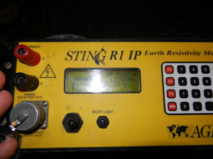
Ministing or Sting R1 Electrical Resistivity Meters
Description:
Both the Ministing and Sting R1 electrical resistivity systems are single channel soil resistivity meters that create a survey by injecting current into the ground and measuring the potential resistance. These surveys are commonly called a sounding or 4 pin survey because two current electrodes and two potential electrodes are used to either inject or receive electrical current. The “true” bulk resistance is calculated using measured values from pairs of electrodes. Like the SuperSting, the electrode spacing controls the effective depth of penetration. These electrical resistivity meters are capable of acquiring data using Wenner, Schlumberger, Dipole-Dipole, Pole-Dipole, Pole-Pole, Mise-A-La-Masse, Self-Potential (SP), Resistance, or Azimuthal arrays. In addition, these electrical resistivity instruments are commonly used for vertical electrical sounding (VES), performing the IEEE Fall-Off-Potential (FOP) methods, four-pin wenner soil test (e.g., ASTM G57), groundwater investigations, cathodic protection design, and grounding studies.
Both the Ministing and Sting R1 are rugged yet lightweight electrical resistivity instruments. They have internal batteries that should last a full day if completely charged with the provided charger. The menus are easy to use and intuitive. Data is saved directly to the instrument and can be transferred to a computer via a data cable and administrative software if needed.
Sting R1 Electrical Resistivity Specifications:
Technical specification
Measurement modes: Apparent resistivity, resistance, voltage, battery voltage
Measurement ranges: 400 kohms to 0.1 milliohm (resistance) 0-500 V full scale autoranging (voltage)
Measuring resolution: max 30 nV, depends on voltage level
Screen resolution: 4 digits in engineering notation.
Output current: 1-2-5-10-20-50-100-200-500 mA,
Output voltage: The user can switch between high and low voltage limit for the transmitter (800 Vp-p or 320 Vp-p voltage limit). Actual electrode voltage depends on transmitted current and ground resistivity. Instrument always starts up in low voltage setting.
Input gain ranging: Automatic, always uses full dynamic range of receiver.
Input impedance: >20 Mohms
Input voltage: Max 500 V
SP compensation: Automatic cancellation of SP voltages during resistivity measurement. Constant and linearly varying SP cancels completely.
Measure cycles: Running average of measurement displayed after each cycle. Automatic cycle stops when reading errors fall below user set limit or user set max cycles are done.
Cycle time: Basic measure time is 1.2, 3.6, 7.2 or 14.4 s as selected by user via keyboard. Autoranging and commutation adds about 1.4 s.
Signal processing: Continuous averaging after each complete cycle. Noise errors calculated and displayed as percentage of reading. Reading displayed as resistance (V/I) and apparent resistivity (m or ft). Resistivity is calculated using user entered electrode distances.
Noise suppression: better than 100 dB at f>20 Hz better than 120 dB at power line frequencies (16 2/3, 20, 50 & 60 Hz)
Total accuracy: Better than 1% of reading in most cases (lab measurements). Field measurement accuracy depends on ground noise and resistivity. Instrument will calculate and display running estimate of measuring accuracy.
System calibration: Calibration is done digitally by the microprocessor based on correction values stored in memory. The correction values are found in final production testing and are also established during later periodical recommended yearly checks at authorized service centers.
Data storage: Full resolution reading average and error are stored along with user entered coordinates and time of day for each measurement. Storage is automatic.
Memory capacity: Over 3000 measuring points can be stored in the internal memory.
Data transmission: RS-232C channel available to dump data from instrument to PC computer on user command. PC program supplied with instrument.
Communication setting: 4800 baud, 8 data bits, no parity, 1 stop bit
User controls: 20 key tactile, weather proof keyboard with numeric entry keys and function keys.
ON/OFF switch.
MEASURE button integrated within main keyboard.
LCD contrast adjustment.
LCD night light switch (push to light)
Display: Alphanumeric LCD display (4 lines x 20 characters). Used for display of results and menus. Night light by LED backlight panel available on switch operation.
Connectors: 4 banana plug pole screws for current and potential electrodes.
10-pole KPT connector for external power, charge, RS-232 and synch connections.
KPT connector signals:
A Transmit RS-232 data
B Battery (-)
C Battery (+)
D –
E +5V supply out for external units
F Receive RS-232 data
G Signal ground
H Synchronization input and remote start
J –
K Synchronization output
Power supply: 12 V, 5 Ah NiCd rechargeable snap-on battery. External power connector on front panel, the instrument automatically selects external battery if present.
Operating time: Depends on conditions. At 20 mA output current and 10 kΩ electrode resistance more than 2000 cycles are available from a fully charged battery pack.
Battery charger: Dual stage charger with switchable input (115/230 V AC @ 50/60 cycles).
Instrument dimensions: Width 112 mm (4.4″), length 293 mm (11.54″) and height 308 mm (112.11″).
Instrument weight: 6.6 kg (14.5 lb) including snap-on battery pack.
Ministing Electrical Resistivity Specifications:
Measurement modes: Apparent resistivity, resistance, voltage (SP), induced polarization (IP), battery voltage
Measurement range: 400 kn to 0.1 millin (resistance) 0-500 V full scale voltage autoranging.
Measuring resolution: Max 30 nV, depends on voltage level
Screen resolution: 4 digits in engineering notation
Output current: 1-2-5-10-20-50-100-200-500 rnA.
Output voltage: The user can switch between high and low voltage limit for the transmitter (800 Vp-p or 320 Vp-p voltage limit). Actual electrode voltage depends on transmitted current and ground resistivity.
Input gain ranging: Automatic, always uses full dynamic range of receiver.
Input impedance: >20Mn
Input voltage: Max 500 V
SP compensation: Automatic cancellation of SP voltages during resistivity measurement. Constant and linearly varying SP cancels completely.
Type of IP measurement: Time domain chargeabilitiy (M), six time slots measured and stored in memory
IP current transmission: ON+, OFF, ON-, OFF
IP time cycles: 1 s. 2 s, 4 s and 8 s
Measure cycles: Running average of measurement displayed after each cycle. Automatic cycle stop when reading errors fall below user set limit or user set max cycles are done.
Cycle time: Basic measure time is 1.2, 3.6, 7.2 or 14.4 s as selected by user via keyboard. auto ranging and commutation adds about 1.4 s.
Signal processing: Continuous averaging after each complete cycle. Noise errors calculated and displayed as percentage of reading. Reading displayed as resistance (dV/1) and apparent resistivity (nm).
Noise suppression: Resistivity is calculated using user entered electrode array coordinates.
Better than 120 dB at power line frequencies (16 2/3, 20, 50 and 60Hz).
Total accuracy: Better than 1% of reading in most cases (lab measurements). Field measurement accuracy depends on ground noise and resistivity. Instrument will calculate and display running estimate of measuring accuracy.
System calibration: Calibration is done digitally by the microprocessor based on correction values stored in memory.
Supported configurations: Resistance, Schlumberger, Wenner, dipole-dipole, pole-dipole, pole-pole, azimuthal, mise-a-lamasse, SP (absolute) and SP (gradient).
Data storage: Full resolution reading average and error are stored along with user entered coordinates and time of day for each measurement. Storage is effected automatically.
Memory capacity: More than 3000 measuring points can be stored in internal memory.
Data transmission: RS-232C channel included to dump data from instrument to PC on user command.
Automatic multi-electrodes: The MiniSting is designed to run dipole-dipole surveys completely automatic with the optional Swift Dual Mode Automatic Multi-electrode system (patent 6,404,203). The MiniSting/Swift can run any other array (Schlumberger, Wenner etc.) by using special user programmed command files. These files are created in an MS DOS type computer and downloaded to the MiniSting RAM memory and are later recalled and run in the field. Therefore there is no need for a fragile computer in the field.
User controls: 20 key tactile, weather proof keyboard with numeric entry keys and function keys.
On/off switch r
Measure button, integrated within main keyboard.
LCD night light switch (push to light).
Display: Alphanumeric LCD display (4 lines x 20 characters) with night light.
Connectors: 4 banana plug, pole screws for current and potential electrodes. 3-pole KPT connector for external power, 1 0-pole KPT connector for RS-232C and synchronization connections.
Power supply: 12V, 4.5 Ah NiMH built-in rechargeable battery. External power connector on front panel, the instrument automatically selects external battery if present.
Operating time: Depends on conditions, internal circuitry in auto mode adjusts current to save energy. At 20 rnA output current and 10 kn electrode resistance more than 2000 cycles are available from a fully charged battery pack.
Battery charger: Dual stage charger with switchable input (115/230 V AC @ 50/60 cycles)
Weight: 6.6 kg (14.5 lb.)
Dimensions: Width 255 mm (10″), length 255 mm (10″) and height 123 mm (5″)
Typical packing list of items received when renting a Ministing or Sting R1 electrical resistivity system:
1 x MiniSting R1 or Sting R1 Console
1 x Cable (Computer to Sting Console)
1 x USB Adaptor Cable
1 x AGI software and manuals on USB Flash Drive
1 x Battery Charger
1 x Cable (Console to External 12 Volt Battery)
1 x Calibration Cable
2 x Current Cable
2 x Potential Cable
4 x Jumper cable 1.8 m (Cable Reels to Electrodes)
4 x Stainless Steel Electrodes
*1 x Shipping Case (24”x20”x10”, 35lbs)
*1 x Shipping Case for Spools (28”x22”x18, weight depends on spool size)
*All dimensions are approximate and will vary depending on configuration and how each instrument is packed. Some shipping containers may be slightly larger/heavier than others containing the same instrument.
Suggested Items:
Hammer to drive electrodes into ground.
Access to water in case the electrode does not couple to ground.
Items you may need to provide:
Several 300ft tape measures depending on size of survey.
12V deep cycle marine battery (Generally not needed, but would work if internal battery is insufficient.)
Computer if you need to download data.
Electrical Resistivity Software provided:
Administrative software for the Ministing and Sting R1 is provided on a USB flash drive.
Electrical Resistivity Rental Rates:
The AGI Ministing or Sting R1 electrical resistivity system rents for $55 per day or $1,320 per month with a $60 prep fee.
*** As a courtesy, we do not charge rent if the equipment is shipped on a Friday and in-transit with FedEx or UPS over Saturday, Sunday, and/or an approved holiday (only valid for rentals less than a month). In its sole and absolute discretion, Geophysical Equipment Rental LLC and/or K. D. Jones Instrument Corp reserve the right not to extend this courtesy.
Get an estimate to rent the Ministing or Sting R1.
User Manual:
Geometrics OhmMapper capacitance coupled towed electrical resistivity array
Description:
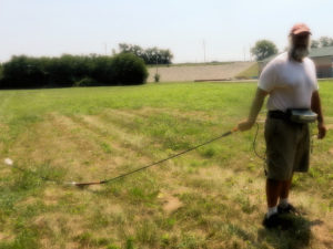
The OhmMapper is a capacitively-coupled electrical resistivity system that does not use metal electrodes to drive into the ground. Unlike DC resistivity equipment, the OhmMapper electrical resistivity system produces a current in the ground with a dipole transmitter. The transmitter couples with the ground, producing a measurable voltage to the OhmMapper’s receiver that varies depending on the composition of the subsurface.
Coaxial cables connect to the transmitter and to the receiver, which create dipoles. The transmitter and receiver sections are separated by a non-conductive rope. The array is often pulled along the ground by a single person or ATV. In contrast to traditional electrical resistivity surveys, this non-electrode approach allows for much faster electrical resistivity surveys since it takes readings while being towed. In other words, there is no timely set-up period for planting electrodes and putting out long cables.
Multiple passes with the OhmMapper or a single pass with multiple receivers at different transmitter to receiver spacings permit more detailed 2-D and even 3-D electrical resistivity surveys at a fraction of the time of traditional electrode based resistivity methods.
OhmMapper Electrical Resistivity Specifications:
Operating Principle: Constant-current capacitively-coupled, dipole-dipole resistivity
Operating Range: 1 – 100,000 Ω m
Cycle Rate: 2 Hz
Data Storage: 2 Mbytes of nonvolatile RAM
Audio Output: Metronome, signal amplitude, disconnect
Visual Output: 320 x 200 LCD
Data Display: 5 line-profiles of resistivity
Output: ASCII columnar
Clock Resolution: 0.1 sec; drift <1 sec/day
Transmitter Frequency: <18 kHz
Transmitter Output Current: Variable from 16 mA to 0.25 mA
Dipole lengths: 5, 10, 15, 20 m; longer lengths optional
Receiver Input: 5 Mhos
Voltage Accuracy: 1%
Receiver Input: 0-2 Vrms
Power Line Rejection: >100 dB
Transmitter/receiver Power: 12 VDC (supplied by console)
Console Power: 28 VDC (Internal battery backup for clock and nonvolatile RAM)
Array Type: Dipole-dipole
Console Weight: 1.6 kg (3.5 lb)
Transmitter Weight: 2 kg (4.4 lb)
Receiver Weight: 2 kg. (4.4 lb)
Battery Pack and Harness: 1.6 kg (3.5 lb)
Array Depressor Weight: 3 kg (6.6 lb)
Console Dimensions: L: 15 cm; W: 8 cm; H: 28 cm (5.9×3.1×11 in)
Battery Dimensions: L: 8 cm; W: 14 cm; H: 20 cm (3.1×5.5×7.9 in)
Typical packing list of items received when renting an OhmMapper electrical resistivity system:
1 x OhmMapper/MagMapper Gradiometer Console
1 x Console Interface Cable with Tow Bar
1 x Receiver
1 x Transmitter
1 x Fiberglass Rod With Optical Coupler
2 x 2.5 meter cables
4 x 5 meter cables
3 x 10 meter cables
5 x Cable Termination Plugs With Metal Spring Clips
1 x Battery Charger for Transmitter and Receiver Batteries With AC Cord
1 x Battery Charger for 24V Console Batteries With AC Cord
1 x Weight
2 x 24V Belt Battery Packs for Console
8 x 6V Batteries for Transmitter and Receiver
3 x Large Rubber Skid Plates
3 x Small Rubber Skid Plates
1 x Software USB Flash Drive
1 x Allen wrench
1 x Download Cable
*2 x Gray Reinforced Plastic Carrying Cases (TBD)
*1 x Red Shipping Tote (28”x22”x18”, 60lbs)
*1 x Cardboard Shipping Boxes (34”x17”x15”, 80lbs)
*All dimensions are approximate and will vary depending on configuration and how each instrument is packed. Some shipping containers may be slightly larger/heavier than others containing the same instrument.
Suggested Items:
Hemisphere GPS
Items you may need to provide:
ATV vehicle if doing large areas of land.
Inverter to charge batteries.
Electrical Resistivity Software provided:
The Geometrics OhmMapper comes with MagMapper to download the data. Res2D can be rented at an additional cost.
Electrical Resistivity Rental Rates:
The Geometrics OhmMapper electrical resistivity system with one set of cables (1, 2.5, 5, or 10 meter cables) rents for $175 per day or $4,200 per month with a $175 prep fee.
Each additional set of Geometrics OhmMapper electrical resistivity cables (1, 2.5, 5, or 10 meter cables) rents for $25 per day or $600 per month with a $30 prep fee.
*** As a courtesy, we do not charge rent if the equipment is shipped on a Friday and in-transit with FedEx or UPS over Saturday, Sunday, and/or an approved holiday (only valid for rentals less than a month). In its sole and absolute discretion, Geophysical Equipment Rental LLC and/or K. D. Jones Instrument Corp reserve the right not to extend this courtesy.
Get an estimate to rent the OhmMapper